Penetration
You can insert a penetration component at the location where a pipe passes through a hull plate. This action automatically creates a hole request that can be sent to the software that created the hull plate, In contrast, inserting a penetration as an into-line or onto-line part by selecting Piping tab > Insert > Component does not create a hole request.
You can create penetrations for one or several pipes at one go. To create multiple penetrations along a pipeline, make sure Auto-select others in spool is enabled so the entire pipe is selected. The penetration component acts as a trigger object for the hole request.
Do the following:
-
Select Piping tab > Penetration group > Insert > Penetration.
-
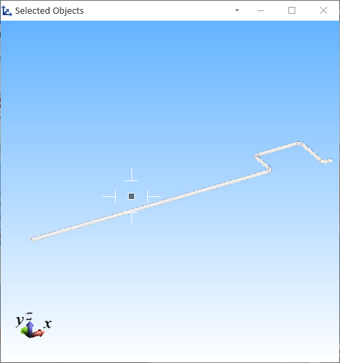
Select one or more pipes that penetrate a hull plate. The pipes are highlighted in the model. If Show selection (S) is enabled in the context menu, the Selected Objects view opens, showing the pipes.
-
Press Enter to accept the selection. If penetrations can be added, the following happens:
-
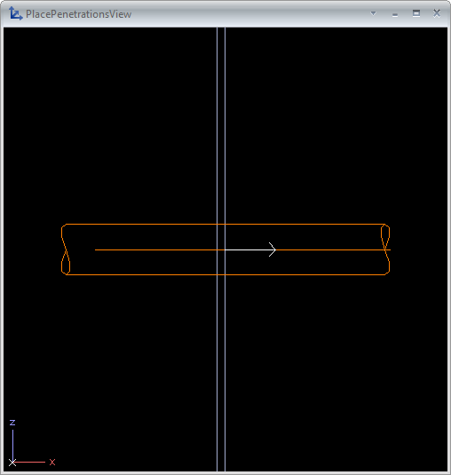
PlacePenetrationsView opens, showing a close-up view of the first pipe–plate intersection and the orientation of the penetration component (relevant for asymmetric components).
-
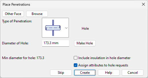
The Place Penetrations dialog opens, allowing you to create a hole with or without a penetration component.
-
-
To inspect the location in the 3D model, click Browse. To return to the Place Penetrations dialog, first press Tab if PlacePenetrationsView is hidden behind the work view, then press Space or Esc.
-
Decide whether to create a hole in the displayed location:
-
To proceed to the next location, click Skip.
-
To create a hole without a penetration component, specify its diameter and click Make Hole.
-
To create a hole with a penetration component, define the settings below and click Create.
 Show/hide details
-
Other Face – For asymmetric components, specify which side of the plate is the reference face. The views show an arrow indicating the current reference face. Click Other Face to change it.
-
Type of Penetration – Select one of the Piping penetration types supported by the current pipe's default specification.
-
Diameter of Hole – Specify the hole diameter. The default value is retrieved from the dimensions of the pipe or penetration component.
-
Include insulation in hole diameter – Select to create a larger hole that includes pipe insulation.
-
Assign attributes to hole request – Select to assign attributes to the hole request.
-
-
-
If you inserted a penetration component that includes instance parameters, you are prompted to define parameter values.
-
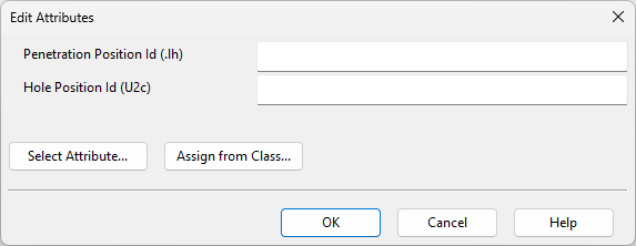
If you chose to assign attributes to the hole request, the Edit Attributes dialog opens. Specify attribute values, and click OK.
-
When all potential penetration locations in the selected pipes have been processed, the tool closes automatically. To submit hole requests to hull designers, open the Hole Manager and select Send Request.